Applicability of test methods
General
Two main groups of test series are established for testing the mechanical and physical properties of fasteners specified in Table 3, FF and MP. Whereas group FF is used for testing finished fasteners, group MP is used for testing material properties of the fasteners. The two groups are divided into test series FF1, FF2, FF3 and FF4, and MP1 and MP2, respectively, for different types of fasteners. However, not all mechanical and physical properties specified in Table 3 can be tested on all types or sizes of fasteners due primarily to dimensional and/or loadability reasons.
Loadability of fasteners
Fasteners with full loadability
A fastener with full loadability is a finished fastener, standardized or non-standardized, which, when tensile tested in accordance with the test series FF1, FF2 or MP2,
a) breaks
⎯ in the free threaded length for fasteners with ds > d2, or
⎯ in the free threaded length or in the unthreaded shank for fasteners with ds ≈ d2, and
b) meets the minimum ultimate tensile load, Fm,min, in accordance with Tables 4 or 6.
Fasteners which, due to their geometry, have reduced loadability
A fastener with reduced loadability is a finished fastener, standardized or non-standardized, with material properties in accordance with property classes as specified in this part of ISO 898 which, due to its geometry, does not fulfil the test requirements for loadability when tested in accordance with test series FF1, FF2 or MP2.
A fastener with reduced loadability does not normally break in the free threaded length when tensile tested in accordance with test series FF3 or FF4.
Basically, there are two geometrical reasons for reduced loadability of fasteners compared with the ultimate tensile load of the thread:
a) a head design which applies to bolts and screws with:
⎯ low head with or without external driving feature,
⎯ low round head or low cylindrical head with internal driving feature, or
⎯ countersunk head with internal driving feature;
b) a shank design which applies to fasteners which are especially designed for applications where the loadability in accordance with this part of ISO 898 is not required or even not desired, e.g. screws with waisted shank.
Test series FF3 (see Table 10) is used for the fasteners mentioned in a), above, while FF4 (see Table 11) is used for those fasteners mentioned in b).
Manufacturer’s test/inspection
Fasteners produced in accordance with this part of ISO 898 shall be capable of conforming to all applicable requirements of Tables 3 to 7 when using the “feasible” tests specified in Tables 8 to 11.
This part of ISO 898 does not mandate which of the tests the manufacturer shall perform on each manufacturing lot. It is the responsibility of the manufacturer to apply suitable methods of his (or her) choice, such as in-process test or inspection, to ensure that the manufactured lot does conform to all of the applicable requirements.
Supplier’s test/inspection
Suppliers may test the fasteners they provide using the methods of their choice, provided the mechanical and physical properties specified in Tables 3 to 7 are met.
Feasible tests for groups of fasteners and machined test pieces
General
The applicability of test series FF1 to FF4 and MP1 to MP2, using the test methods is specified in Tables 8 to 13.
Test series FF1 to FF4 in accordance with Tables 8, 9, 10 and 11 are provided for the testing of finished fasteners:
⎯ FF1: these are tests for the determination of the properties of finished bolts and screws with full head strength and full or reduced shank (full loadability), ds > d2 or ds ≈ d2 (see Table 8);
⎯ FF2: these are tests for the determination of the properties of finished studs with full or reduced shank (full loadability), ds > d2 or ds ≈ d2 (see Table 9);
⎯ FF3: these are tests for the determination of the properties of finished bolts and screws with ds > d2 or ds ≈ d2 and reduced loadability due to
1) low head with or without external driving feature,
2) low round head or low cylindrical head with internal driving feature, or
3) countersunk head with internal driving feature (see Table 10);
⎯ FF4: these are tests for the determination of the properties of finished bolts, screws and studs especially designed for applications where the full loadability in accordance with this part of ISO 898 is not required or not desired, e.g. fasteners with waisted shank (reduced loadability), ds < d2 (see Table 11).
Test series MP1 and MP2 in accordance with Tables 12 and 13 are provided for testing the material properties of fasteners and/or for process development. Test series FF1 to FF4 may also be used for that purpose.
⎯ MP1: these are tests for the determination of the material properties of fasteners and/or for process development using machined test pieces (see Table 12).
⎯ MP2: these are tests for the determination of material properties of fasteners with full loadability, ds ≈ d2 or ds > d2, and/or for process development (see Table 13).
Table 8 — Test series FF1 — Finished bolts and screws with full loadability
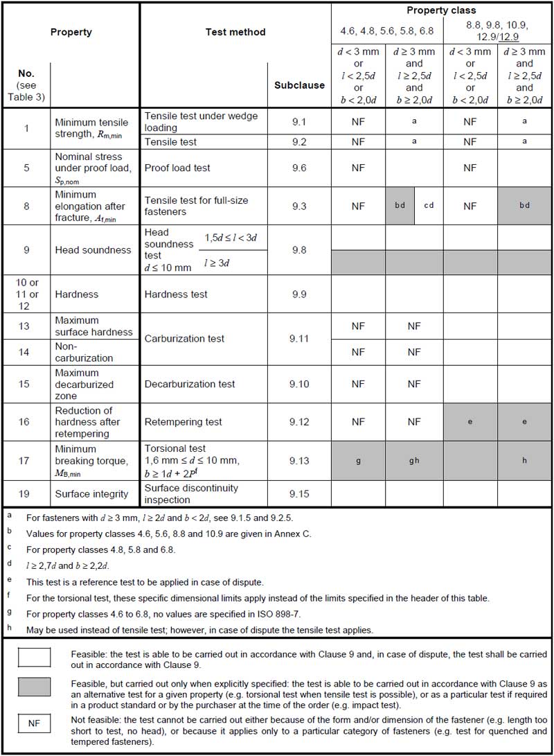
Table 10 — Test series FF3 — Finished screws with reduced loadability due to head design

Table 11 — Test series FF4 — Finished bolts, screws and studs with reduced loadability due to shank design (e.g. waisted shank)
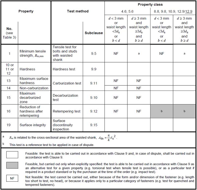
Table 12 — Test series MP1 — Material properties determined on machined test pieces

Table 13 — Test series MP2 — Material properties determined on finished fasteners with full loadability

Test methods
Tensile test under wedge loading of finished bolts and screws (excluding studs)
General
The purpose of this tensile test is to determine simultaneously:
⎯ the tensile strength on finished bolts and screws, Rm;
⎯ the integrity of the transition section between the head and the unthreaded shank or the thread.
Applicability
This test applies to bolts and screws with or without flange having the following specifications:
⎯ flat bearing surface or serrated surfaces;
⎯ head stronger than the threaded section;
⎯ head stronger than any unthreaded shank;
⎯ diameter of any unthreaded shank, ds > d2 or ds ≈ d2;
⎯ nominal length, l ≥ 2,5d;
⎯ thread length, b ≥ 2,0d;
⎯ structural bolts with b < 2d;
⎯ 3 mm ≤ d ≤ 39 mm;
⎯ all property classes.
Apparatus
The tensile testing machine shall be in accordance with ISO 7500-1. Tooling features altering the effect of the wedge angle, α, as specified in Figure 1 and Table 16 shall not be used.
Testing device
The grips, the wedge and the adaptors shall be in accordance with the following:
⎯ hardness of 45 HRC min;
⎯ thread tolerance class of the internally threaded adaptor in accordance with Table 14;
⎯ hole diameter, dh, in accordance with Table 15;
⎯ wedge in accordance with Figure 1 and Tables 15 and 16.
Table 14 — Thread tolerance classes of internally threaded adaptors
| Finish of fastener | Thread tolerance class | |
| Thread tolerance class of fastener before any surface coating |
Thread tolerance class of internally threaded adaptor |
|
| As processed | 6h or 6g | 6H |
| Electroplating to ISO 4042 | 6g or 6e or 6f | 6H |
| Zinc flake coating to ISO 10683 | 6g or 6e or 6f | 6H |
| Hot dip galvanizing to ISO 10684 in order to mate with nuts tapped to thread tolerance classes:⎯ 6H⎯ 6AZ⎯ 6AX |
6az
6g or 6h 6g or 6h |
6H
6AZ 6AX |
The testing device shall be sufficiently rigid to ensure that bending occurs in the transition section between the head and the unthreaded shank or the thread.
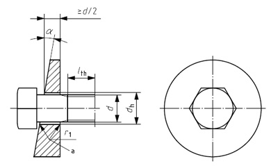
Table 15 — Hole diameters and radius for the wedge
Dimensions in millimetres
| Nominal thread diameter d |
dhab | r1c | Nominal thread diameter d |
dhab | r1c | ||
| min. | max. | min. | max. | ||||
| 3 | 3,4 | 3,58 | 0,7 | 16 | 17,5 | 17,77 | 1,3 |
| 3,5 | 3,9 | 4,08 | 0,7 | 18 | 20 | 20,33 | 1,3 |
| 4 | 4,5 | 4,68 | 0,7 | 20 | 22 | 22,33 | 1,6 |
| 5 | 5,5 | 5,68 | 0,7 | 22 | 24 | 24,33 | 1,6 |
| 6 | 6,6 | 6,82 | 0,7 | 24 | 26 | 26,33 | 1,6 |
| 7 | 7,6 | 7,82 | 0,8 | 27 | 30 | 30,33 | 1,6 |
| 8 | 9 | 9,22 | 0,8 | 30 | 33 | 33,39 | 1,6 |
| 10 | 11 | 11,27 | 0,8 | 33 | 36 | 36,39 | 1,6 |
| 12 | 13,5 | 13,77 | 0,8 | 36 | 39 | 39,39 | 1,6 |
| 14 | 15,5 | 15,77 | 1,3 | 39 | 42 | 42,39 | 1,6 |
| a Medium series in accordance with ISO 273.
b For square neck bolts, the hole shall be adapted to accommodate the square neck. c For product grade C, a radius, r1, should be used in accordance with the following formula: r1 = rmax + 0,2 where rmax = da,max – ds,min / 2 |
|||||||
Table 16 — Wedge angle, α, for tensile test under wedge loading
| Nominal thread diameter d |
Property class for | |||
| bolts and screws with unthreaded shank length ls ≥ 2d |
screws threaded to the head and bolts and screws with unthreaded shank length ls < 2d |
|||
| 4.6, 4.8, 5.6, 5.8, 6.8, 8.8, 9.8, 10.9 |
12.9/12.9 | 4.6, 4.8, 5.6, 5.8, 6.8, 8.8, 9.8, 10.9 |
12.9/12.9 | |
| α ± 30′ | ||||
| 3 ≤ d ≤ 20 | 10° | 6° | 6° | 4° |
| 20 < d ≤ 39 | 6° | 4° | 4° | 4° |
For finished bolts and screws with head-bearing diameters above 1,7d that fail the wedge tensile test, the head may be machined to 1,7d and re-tested on the wedge angle specified in Table 16.
Moreover, for finished bolts and screws with head-bearing diameters above 1,9d, the 10° wedge angle may be reduced to 6°.
Test results
Determination of tensile strength, Rm
Method
The calculation of the tensile strength, Rm, is based on the nominal stress area, As,nom, and the ultimate tensile load, Fm, measured during the test:
Rm = Fm / As,nom
with
As,nom = π/4{d2+d3/2}2
where
d2 is the basic pitch diameter of external thread in accordance with ISO 724;
d3 is the minor diameter of external thread
d3 = d1 – H/6
d1 is the basic minor diameter of external thread in accordance with ISO 724;
H is the height of the fundamental triangle of the thread in accordance with ISO 68-1.
Values of the nominal stress area, As,nom, are given in Tables 4 and 6.
Requirements
For bolts and screws with ds > d2 and screws threaded to the head, the fracture shall occur in the free threaded length.
For fasteners with ds ≈ d2, the fracture shall occur in the free threaded length or in the unthreaded shank.
Rm shall meet the requirements specified in Table 3. The minimum ultimate tensile load, Fm,min, specified in Tables 4 and 6 shall be met.
NOTE With small diameters, there is an increasing difference between the nominal stress area compared to the effective stress area. When hardness is used for process control/testing, especially for smaller diameters, it can be necessary to increase the hardness above the minimum hardness specified in Table 3 to achieve the minimum ultimate tensile load.
Determination of integrity of transition section between head and unthreaded shank/thread — Requirements
The fracture shall not occur in the head.
For bolts and screws with unthreaded shank, the fracture shall not occur in the transition section between the head and the shank.
For screws threaded to the head, the fracture that causes failure may extend or spread into the transition section between the head and the thread, or into the head, before separation, provided it originates in the free threaded length.
Tensile test for finished bolts, screws and studs for determination of tensile strength, Rm
General
The purpose of this tensile test is to determine the tensile strength on finished fasteners, Rm.
Applicability
This test applies to bolts, screws and studs having the following specifications:
⎯ bolts and screws with head stronger than the threaded shank;
⎯ bolts and screws with head stronger than any unthreaded shank;
⎯ diameter of any unthreaded shank of ds > d2 or ds ≈ d2;
⎯ bolts and screws with nominal length l ≥ 2,5d;
⎯ thread length b ≥ 2,0d;
⎯ structural bolts with b < 2d;
⎯ studs with total length lt ≥ 3,0d;
⎯ 3 mm ≤ d ≤ 39 mm;
⎯ all property classes.
Apparatus
The tensile testing machine shall be in accordance with ISO 7500-1. Side thrust on the fastener shall be avoided, e.g. by self-aligning grips.
Testing device
The grips and the adaptors shall be as follows:
⎯ hardness, 45 HRC min;
⎯ hole diameter, dh, in accordance with Table 15;
⎯ thread tolerance class of the internally threaded adaptor(s) in accordance with Table 14.

Test results
Determination of the elongation after fracture, Af
Method
The plastic elongation, ΔLp, is measured directly on the load-displacement curve, plotted either electronically or graphically (see below figure).
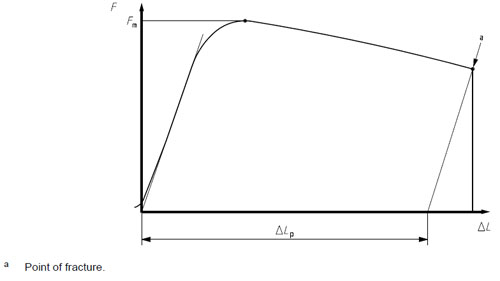
The slope of the part of the curve corresponding to the elastic range (straight part of the curve) shall be determined. A line parallel to the slope in the elastic range shall be drawn through the point of fracture, which has an intersecting point with the grip displacement axis (above figure). The plastic elongation, ΔLp, is determined on the grip displacement axis in accordance with above figure.
In case of doubt, the slope of the load-displacement curve in the elastic range shall be determined by drawing a line intersecting the two points of the curve corresponding to 0,4 Fp and 0,7 Fp, where Fp is the proof load as specified in Tables 5 and 7.
The elongation after fracture on full-size fasteners is calculated using Formula
Af = ΔLp / 1,2d
Determination of the stress at 0,0048d non-proportional elongation, Rpf
Method
Rpf shall be directly determined on the load-displacement curve (see below figure).
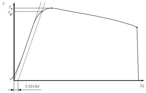
A parallel line to the slope in the elastic range (straight part of the curve) shall be drawn at a distance equal to 0,0048d on the axis of grip displacement; the intersection between this line and the curve corresponds to the load Fpf.
NOTE 0,0048d = 0,4 % of 1,2d.
In case of doubt, the slope of the load-elongation curve in the elastic range shall be determined by drawing a line intersecting the two points of the curve corresponding to 0,4 Fp and 0,7 Fp, where Fp is the proof load as specified in Tables 5 and 7.
The stress at 0,0048d non-proportional elongation, Rpf, is calculated using Formula
Rpf = Fpf / As,nom
Tensile test for bolts and screws with reduced loadability due to head design
General
The purpose of this tensile test is to determine the tensile load for bolts and screws with reduced loadability, i.e. not expected to break in the free threaded length due to head design.
9.4.2 Applicability
This test applies to bolts and screws having the following specifications:
⎯ not expected to break in the free threaded length due to head design;
⎯ diameter of any unthreaded shank ds > d2 or ds ≈ d2;
⎯ nominal length l ≥ 2,5d;
⎯ thread length b ≥ 2,0d;
⎯ 3 mm ≤ d ≤ 39 mm;
⎯ all property classes.
Apparatus
The tensile testing machine shall be in accordance with ISO 7500-1. Side thrust on the fastener shall be avoided, e.g. by self-aligning grips.
Testing device
The grips and the adaptors shall be as follows:
⎯ hardness of 45 HRC min;
⎯ hole diameter, dh, in accordance with Table 15;
⎯ thread tolerance class of the internally threaded adaptor in accordance with Table 14.
Test procedure
The fastener shall be tested as received.
The bolt or screw to be tested shall be mounted into adaptors.
The free threaded length, lth, subjected to the load shall be a minimum of 1d.
The tensile test shall be carried out in accordance with ISO 6892-1. The speed of testing, as determined with a free-running cross-head, shall not exceed 25 mm/min.
The tensile test shall be continued until fracture occurs.
The ultimate tensile load, Fm, shall be measured.
Test results — Requirements
The ultimate tensile load, Fm, shall be equal to or above the minimum ultimate tensile load as specified in the relevant product standard or other relevant specification.
Tensile test for fasteners with waisted shank
General
The purpose of this tensile test is to determine the tensile strength, Rm, for fasteners with waisted shank.
Applicability
This test applies to fasteners having the following specifications:
⎯ diameter of unthreaded shank ds < d2;
⎯ length of waisted shank ≥ 3ds;
⎯ thread length b ≥ 1d;
⎯ 3 mm ≤ d ≤ 39 mm;
⎯ property classes 4.6, 5.6, 8.8, 9.8, 10.9 and 12.9/12.9.
Apparatus
The tensile testing machine shall be in accordance with ISO 7500-1. Side thrust on the fastener shall be avoided, e.g. by self-aligning grips.
Testing device
The grips and the adaptors shall be as follows:
⎯ hardness of 45 HRC min;
⎯ hole diameter, dh, in accordance with Table 15;
⎯ thread tolerance class of the internally threaded adaptor(s) in accordance with Table 14.
9.5.5 Test procedure
The fastener shall be tested as received.
The bolt to be tested shall be mounted into an adaptor. The stud to be tested shall be mounted into two threaded adaptors. The length of thread engagement shall be at least 1d.
The tensile test shall be carried out in accordance with ISO 6892-1. The speed of testing, as determined with a free-running cross-head, shall not exceed 25 mm/min.
The tensile test shall be continued until fracture occurs.
The ultimate tensile load, Fm, shall be measured.
Test results
Method
The calculation of the tensile strength, Rm, is based on the cross-sectional area of the waisted shank, Ads, and the ultimate tensile load, Fm, measured during the test:
Rm = Fm / Ads
with
Ads = π / 4 . ds2
Proof load test for finished bolts, screws and studs
General
The proof load test consists of two main operations, as follows,
⎯ application of a specified tensile proof load and
⎯ measurement of permanent elongation, if any, caused by the proof load.
Applicability
This test applies to bolts, screws and studs having the following specifications:
⎯ bolts and screws with head stronger than the threaded shank;
⎯ bolts and screws with head stronger than any unthreaded shank;
⎯ diameter of unthreaded shank ds > d2 or ds ≈ d2;
⎯ bolts and screws with nominal length l ≥ 2,5d;
⎯ thread length b ≥ 2,0d;
⎯ studs with total length lt ≥ 3,0d;
⎯ 3 mm ≤ d ≤ 39 mm;
⎯ all property classes.
Apparatus
The tensile testing machine shall be in accordance with ISO 7500-1. Side thrust on the fastener shall be avoided, e.g. by self-aligning grips.
Testing device
The grips and the adaptors shall be in accordance with the following:
⎯ hardness of 45 HRC min;
⎯ hole diameter, dh, in accordance with Table 15;
⎯ thread tolerance class of the internally threaded adaptor(s) in accordance with Table 14.

An example is “sphere to cone” contact between the measuring points and the centre-drilled conical holes in the ends of the fastener is shown in detail X. Any other suitable method may be used.
Tensile test for machined test pieces
General
The purpose of this tensile test is to determine
⎯ the tensile strength, Rm,
⎯ the lower yield strength, ReL, or stress at 0,2 % non-proportional elongation, Rp0,2,
⎯ the percentage elongation after fracture, A, and
⎯ the percentage reduction of area after fracture, Z.
Applicability
This test applies to fasteners having the following specifications:
a) machined test pieces made from bolts and screws:
⎯ 3 mm ≤ d ≤ 39 mm;
⎯ thread length b ≥ 1d;
⎯ nominal length l ≥ 6d0 + 2r + d to determine A;
⎯ nominal length l ≥ 4d0 + 2r + d (as specified in Figure 6) to determine Z;
b) machined test pieces made from studs:
⎯ 3 mm ≤ d ≤ 39 mm;
⎯ thread length b ≥ 1d;
⎯ thread length of the stud metal end bm ≥ 1d;
⎯ total length lt ≥ 6d0 + 2r + 2d to determine A;
⎯ total length lt ≥ 4d0 + 2r + 2d (as specified in Figure 6) to determine Z;
c) property classes 4.6, 5.6, 8.8, 9.8, 10.9 and 12.9/12.9.
NOTE Machined test pieces can be made from fasteners which, due to their geometry, have reduced loadability, provided the head is stronger than the cross-sectional area, So, of the test piece, and also from fasteners with unthreaded shank diameter ds < d2.
Fasteners in property classes 4.8, 5.8 and 6.8 (work-hardened fasteners) shall be tensile tested full-size.
Apparatus
The tensile testing machine shall be in accordance with ISO 7500-1. Side thrust on the fastener shall be avoided, e.g. by self-aligning grips.
Testing device
The grips and the adaptors shall be as follows:
⎯ hardness of 45 HRC min;
⎯ hole diameter, dh, in accordance with Table 15;
⎯ thread tolerance class of the internally threaded adaptor(s) in accordance with Table 14.
Machined test pieces
The test piece shall be machined from the fastener as received.
The diameter of the machined test piece shall be d0 < d3,min, but whenever possible d0 ≥ 3 mm.
When machining the test pieces of quenched and tempered fasteners with nominal diameter d > 16 mm the reduction of the original diameter, d, shall not exceed 25 % (about 44 % of the initial cross-sectional area). For test pieces made from studs, both ends shall have a thread length of minimum 1d.
Test procedure
The tensile test shall be carried out in accordance with ISO 6892-1. The speed of testing, as determined with a free-running cross-head, shall not exceed 10 mm/min up to the load at lower yield strength, ReL, or the load at the stress at 0,2 % non-proportional elongation, Rp0,2, and 25 mm/min beyond.
The tensile test shall be continued until fracture occurs.
The ultimate tensile load, Fm, shall be measured.

Test results
Method
The following properties shall be determined in accordance with ISO 6892-1:
a) tensile strength, Rm
Rm = Fm / So
b) lower yield strength, ReL, or stress at 0,2 % non-proportional elongation, Rp0,2;
c) percentage elongation after fracture, provided Lo is at least 5d0
A = {Lu – Lo / Lo } x 100
where Lu is the final gauge length of machined test piece (see ISO 6892-1);
d) percentage reduction of area after fracture, provided Lo is at least 3d0
Z = {So – Su / So} x 100
where Su is the cross-sectional area of machined test piece after fracture.